• 1275 Harvard Drive, Kankakee, IL 60901, USA
How Coaxial MIG Cable Design Improves Wire Feed and Arc Stability cover

How Coaxial MIG Cable Design Improves Wire Feed and Arc Stability

​Welding relies on two cables that look alike but do opposite jobs. One carries current, gas, and wire feed toward the weld pool. The other returns that current to the power source. These are the MIG cable and the grounding cable. Purchasing teams and OEMs often treat them as interchangeable. They are not. Knowing what separates them helps you spec the right part for each role. That one decision protects weld quality, operator safety, and uptime.

What a MIG Cable Delivers

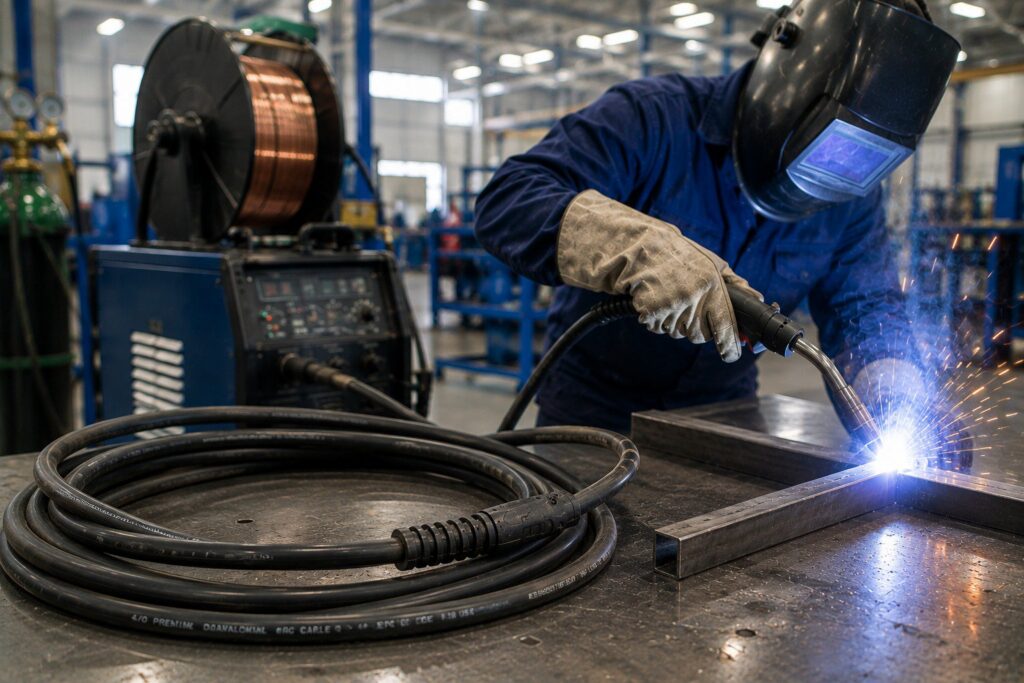
A MIG cable is the working end of the welding circuit. It does far more than carry electricity. The MIG cable bundles several jobs into one flexible assembly. That bundle runs from the wire feeder to the welding gun.
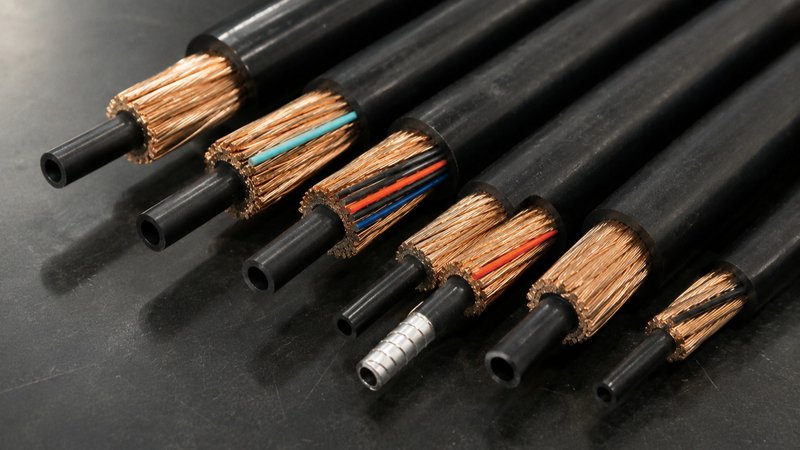
​A well-built MIG cable typically carries:

  • Welding current: Copper conductors move power to the contact tip.
  • Electrode wire: An inner liner guides the feed to the gun.
  • Shielding gas: A gas path protects the molten weld pool.
  • Control signals: Small leads manage trigger and feed response.

Each element depends on the others. A weak jacket or thin conductor drags the whole cable down. The assembly also faces heat, sparks, and constant flexing. Solid construction keeps every layer working through long shifts. The right jacket compound also shrugs off spatter and drips. That protection extends service life on busy production lines. This is why buyers should never treat a MIG cable as a simple wire.

What a Grounding Cable Does

A grounding cable does one job well. It completes the welding circuit. Welders also call it the work cable or return lead. It clamps to the workpiece or the welding table. Current then travels back to the machine safely.

The build is much simpler than a MIG cable. There is no liner. There is no gas path. There are no control leads. A grounding cable is mostly copper and jacket. That focus lets it carry high current with less bulk. Undersized ground cables run hot and waste energy. Correct conductor size keeps the arc stable and the cable cool. Clamp quality matters just as much as the copper. A loose or corroded clamp adds resistance and heat. A clean, tight connection keeps current flowing freely.

Key Differences Between the Two Cables

Function is the clearest divide. A MIG cable feeds the weld. A grounding cable returns the current. Construction then follows function. The MIG cable is a layered, multi-part assembly. The grounding cable is a single focused conductor.
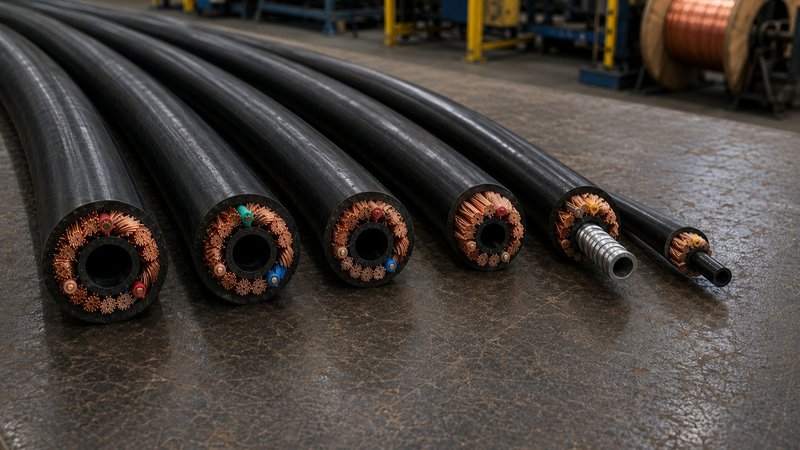
​Handling separates them too. A MIG cable moves with the welder all shift. It needs fine stranding and a tough, flexible jacket. A grounding cable stays mostly in place. It still needs solid conductors and strong abrasion resistance. High duty cycles expose any weakness in either cable. Their failure modes differ as well. A MIG cable often fails at the flex points first. A grounding cable tends to fail at the clamp or connector. Matching each cable to its role reduces downtime. Smart cable construction keeps a whole welding fleet consistent.

Where Wire Feed Fits in the Bigger Picture

Wire feed lives on the MIG side of the circuit. The grounding cable plays no part in it. Steady feed depends on more than the cable, however. The liner, contact tip, and drive rolls all shape the result. These parts wear a little with every shift. Worn parts cause stutter, burnback, and erratic arcs. Operators usually feel these problems before they see them. A quick check of the liner and tip catches most issues early. Catching wear early keeps the whole line moving.

This is where feed components and consumables earn their keep. They are small parts with a large impact. Fresh liners and tips protect the entire weld. A simple replacement schedule prevents most feed problems. Quality consumables also let a good cable perform as designed.

Let Us Match Your Cables and Feed Components

You know your welding process better than anyone. We help you match the right cable to each job. At Electron Beam Technologies, we build custom MIG and grounding cables to your exact specs. We draw our own copper in-house. We mix and cure our own compounds on-site. Our electron beam process strengthens every jacket without harsh chemical accelerants.

Our accessory products line covers the feed components your team relies on. Think the tips, liners, and small parts that wear out first. Everything ships from the USA with short lead times. You skip the import delays and tariff exposure that come with overseas parts. Reach out today and we will build a solution around your bench.

Read More
What Is a Coaxial MIG Cable and Why It Outperforms Traditional Welding Leads cover

What Is a Coaxial MIG Cable and Why It Outperforms Traditional Welding Leads

​MIG welding performance depends on more than technique and machine settings. The welding leads connecting your machine to the torch have a direct impact on arc performance, heat management, and operator efficiency.

Coaxial MIG cable offers a fundamentally different design compared to conventional two-lead setups. It addresses several performance limitations that separate cable assemblies cannot. For procurement managers and engineering teams, understanding this difference translates into better cable specifications and fewer operational problems.

How Coaxial MIG Cable Is Constructed

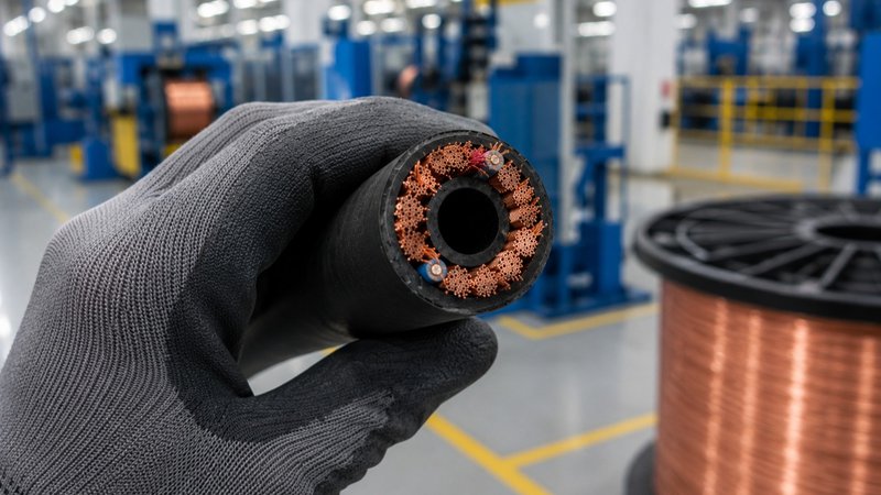
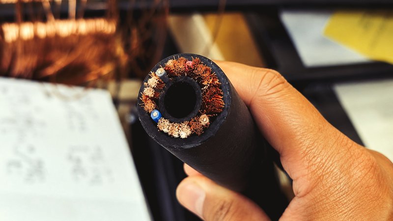
​Coaxial MIG cable is built around a concentric design. At the center of the cable is a hollow tube. This tube carries the inert shielding gas and guides the welding wire on its path to the torch. There is no return current path inside this tube.

​Surrounding that central tube is the copper conductor stranding. This conductor carries the welding current from the machine to the torch. A protective jacket covers the entire assembly.

This layout bundles three functions into one cable. Gas delivery, wire feed, and current flow all travel together. That is the coaxial part of the design. Everything runs concentrically around a shared centerline instead of as separate hoses and cables.

Additional layers refine the cable’s performance. These components typically include:

  • A shielding layer beneath the outer jacket to reduce electrical interference
  • Fillers that maintain the cable’s round cross-section under repeated flexing
  • Separators between layers to prevent conductor contact and preserve cable geometry

Bare copper stranding is also critical to flexibility. Finer strand diameters produce a more supple cable. This suits applications where the welder needs maximum range of motion. Heavier-gauge strands add stiffness, which works well for fixed or semi-fixed installations.

Why Traditional Welding Leads Fall Short

​Every arc welding process needs a complete circuit. That means a lead to the torch or electrode and a separate work return cable back to the machine. This is true for stick, TIG, and MIG welding alike. Coaxial design does not change that requirement.

Where MIG setups differ is in how the torch-side components are managed. In a non-coaxial MIG setup, the gas hose, the wire liner, and the power conductor run as separate parts. They get taped, clipped, or bundled together by hand.

This creates practical problems. Loose components tangle easily on active shop floors. They create trip hazards and slow down welder movement. Cable management takes time away from production.

Wire feed also suffers. A gas hose and power cable that shift independently can pull or kink the wire liner. Tight bends increase friction between the liner and the wire. That friction leads to poor feeding, wire shaving, and more frequent liner replacement.

​Stick welding avoids some of these problems since it has no gas hose or wire liner to manage. TIG welding uses a separate torch lead and gas line, too. That setup is usually lighter than a full MIG gun cable. MIG welding has the most components to coordinate at the torch. That makes bundled cable design especially valuable for MIG applications.

​Welding Leads: Performance Advantages of the Coaxial Design

​Coaxial construction keeps the gas hose, wire liner, and power conductor in a fixed, protected position relative to each other. This reduces the friction and kinking that loose components create.

Consistent wire feed depends on a straight, unobstructed path through the liner. When the liner is bundled inside a coaxial cable, it holds its shape better. Wire feeds more smoothly. Arc starts stay consistent, and burnback problems decrease.

The single-cable format simplifies the workspace. Welders move more freely without managing separate hoses and cables. Setup is faster. There is also only one cable assembly to inspect and replace, which reduces maintenance time in high-volume production environments.

Compared to stick welding, coaxial MIG cable adds a level of bundled convenience. Stick leads stay simpler, but they require constant electrode changes. TIG often separates the gas line from the torch lead. Coaxial MIG cable keeps the whole system in one jacket instead. This matters more as duty cycles and cable lengths increase.

Jacket Materials That Determine Real-World Welding Leads Performance

The outer jacket is the cable’s primary defense against its working environment. Material selection determines how the cable holds up against abrasion, heat, chemicals, and continuous bending. Not all jacket materials perform equally under demanding conditions.

When specifying jacket material, evaluate these properties:

  • Abrasion resistance for cables dragged across rough surfaces or metal debris
  • Flexibility ratings for overhead welding or confined-space applications
  • Sustained temperature resistance for high-duty-cycle operations
  • Chemical resistance where the cable contacts oils, solvents, or cleaning agents

XLPE (cross-linked polyethylene) delivers strong performance across each of these categories. Cross-linking alters the polymer structure at a molecular level. This makes the material more resistant to heat, abrasion, and chemical exposure. XLPE also maintains flexibility without sacrificing toughness. Standard polyethylene cannot match these properties because it lacks the cross-linked structure.

Ready to Specify a Cable Built for Your Operation?

At Electron Beam Technologies, we manufacture custom coaxial MIG cable from the ground up. We draw our own copper and mix our own XLPE compounds in-house. That level of vertical integration gives us precise control over every layer of your cable.

Our electron beam curing process cross-links jacket compounds, strengthening the material from within. This delivers greater durability than conventional chemical curing methods can achieve.

You bring the application requirements. We build the cable to match them. Our U.S.-based manufacturing keeps lead times short and removes the unpredictability of international shipping. If tariffs or supply chain delays are affecting your current sourcing, we can help.

Reach out to our team to start your custom cable specification.

Read More
custom cable construction

What Every Buyer Should Understand About Custom Cable Construction

Choosing the right custom MIG cable construction matters more than many buyers realize. A MIG cable is not just a power cable. It is a multi-part assembly that affects feeding performance, durability, operator movement, and service life. When the construction is generic, small design issues can create major problems on the floor. For OEMs and manufacturers, those problems often show up as downtime, inconsistent weld quality, and premature replacement.

Why Generic Cables Create Problems for Manufacturers

​Standard welding cables are built to cover broad use cases. That approach may work for light-duty applications, but it often fails in equipment with specific bend requirements, duty cycles, or environmental exposure. A cable that is too stiff, too bulky, or poorly matched to the wire feed setup can reduce efficiency fast.

custom cable construction

​Custom construction helps buyers avoid those problems early. It lets the cable match the equipment, the process, and the working environment. That reduces rework and improves consistency over time.

The Core Tube Material and Size Matter

The core tube is one of the most important parts of a MIG cable. It runs down the center of the cable and guides the welding wire during feeding. If the material or size is wrong, wire movement can become inconsistent. That can lead to feeding issues, wear, and poor welding performance.

Buyers should evaluate core tube choices based on the wire type, application, and expected duty cycle.

  • Material choice affects friction, wear resistance, and flexibility.
  • Size choice affects wire travel, feed consistency, and compatibility with the welding setup.
  • A tube that is too tight can restrict feeding, while one that is too large can reduce control.

These details should be matched to the actual use case. A cable supplier should not treat the core tube as a minor component. In MIG cable construction, it directly affects function.

Conductors and Outer Layer Performance

The conductor supports current transfer and overall cable flexibility. Copper quality, strand design, and manufacturing control all play a role in how the cable performs in the field. For high-use applications, consistency in conductor construction helps support long-term reliability.

In this type of cable, the insulation and jacket are the same layer and should be treated as one combined outer layer. That layer protects the cable from heat, abrasion, and shop conditions while also contributing to flexibility. Its material formulation and curing process influence how well the cable holds up under repeated movement and harsh use.

Control Lead Wires and Cable Marking

Many custom MIG cable assemblies also require control lead wires. These wires support trigger functions and other system controls within the overall assembly. Their placement, gauge, and protection should be considered as part of the full cable design, not as an afterthought.

Cable marking can also add practical value for manufacturers and OEMs.

  • Marking can support identification, traceability, and installation accuracy.
  • It can include part numbers, customer-specific information, or other production details.
  • Clear marking helps reduce confusion during assembly, service, and replacement.
custom cable construction

​These features may seem secondary at first. In practice, they can improve workflow and reduce avoidable handling errors.

Matching Construction to the Application

A strong MIG cable design starts with the application. Buyers should look at bend radius, heat exposure, movement, wire type, and equipment layout before settling on a construction. A cable used in a demanding industrial environment should not be built the same way as one used in a lighter-duty setup.

This is where a custom manufacturer creates value. Electron Beam can build MIG cable constructions around specific performance needs rather than forcing buyers into off-the-shelf options. That includes flexibility in conductor design, outer layer performance, core tube configuration, control lead integration, and cable marking.

Build Around Your Specs

Your MIG cable should fit your process, not the other way around. Electron Beam supports custom cable builds with short lead times, domestic manufacturing, and vertically integrated production. That gives you more control over quality, supply, and final cable performance.

If your current cable design is creating feed issues, delays, or fit problems, it may be time to rethink the construction. Start with the actual demands of your application, then build the cable around them. Send us a message to get started.


FAQ

What are the main ways generic cables fail in specialized applications?

Generic jackets often crack when exposed to chemicals. They can also fail under extreme temperature swings. Poorly drawn copper reduces the cable's flex life. This causes premature breakage in high-motion setups.

How does a vertically integrated manufacturer specifically reduce risk?

Vertical integration means the supplier manages every step. They control copper drawing and compound mixing in-house. This removes external vendor delays. It also guarantees quality consistency across all components.

What is the specific benefit of polymer chain cross-linking from Electron Beam curing?

Cross-linking makes the polymer structure denser. This increases resistance to heat and abrasion. It allows for a higher-rated operating temperature. The cable maintains integrity in harsh environments much longer.

Read More
welding cable construction

Why Cable Construction Matters More Than Gauge Alone

When sourcing wire and cable, many buyers focus on one thing first: gauge. Gauge matters, but it does not tell the whole story. Welding cable construction includes much more than conductor size. It also includes strand count, conductor quality, and the insulation jacket system that protects the cable in real use.

That broader construction affects flexibility, service life, and performance on the floor. Two cables with the same gauge can behave very differently in bending, abrasion, heat, and daily handling. Buyers who look beyond gauge are more likely to choose cable that lasts longer and creates fewer production problems.

Welding Cable Construction: Gauge Is Only the First Filter

Gauge tells you the conductor cross section, so it helps determine current capacity. That is important, but it is only a starting point when comparing one cable to another. Welding cables with the same gauge can still perform very differently because the rest of the construction changes how the product works in the field.

welding cable construction

​This is why gauge alone can be misleading during sourcing. A lower cost option may match the required gauge, yet still fall short in flex life or durability. For OEMs and purchasing teams, that can lead to early replacement, downtime, and inconsistent performance.

Welding Cable Construction Details Shape Flex Life

Stranding is one of the biggest reasons two same gauge cables feel and perform differently. A higher strand count usually improves flexibility and helps the cable handle repeated movement. A lower strand count can reduce cost, but it often creates a stiffer cable that is more likely to fatigue in demanding applications.

Other construction details also matter during daily use:

  • Strand count affects bendability and resistance to fatigue.
  • Lay configuration influences how the conductor moves under repeated flexing.
  • Copper quality affects consistency, conductivity, and long term reliability.

Conductor material also plays a role. Bare copper is common in many applications and supports strong electrical performance. Tinned copper can improve corrosion resistance in harsher environments, but it comes at a higher cost, so it is not always the right fit for the job.

The Insulation Jacket Sets the Balance

In this application, insulation and jacketing should not be treated as two separate design discussions. They function as one insulation jacket system that helps protect the conductor from heat, abrasion, and the surrounding environment. If that system is poorly matched to the job, the cable can wear out early even when the gauge is correct.

This is also where the tradeoff between durability and flexibility becomes important. A tougher XLPE jacket can improve abrasion resistance and thermal stability, but every design still has to balance ruggedness with the level of flexibility the application needs. If the jacket is too rigid, handling and repeated movement can suffer. If it is too soft, the cable may not hold up well in rough service.

welding cable construction

​The curing method matters here as well. Electron beam curing creates a more cross linked structure in the jacket material. That helps the insulation jacket system resist abrasion and heat more effectively over time, which supports longer service life in demanding environments.

Custom Construction Lowers Risk

Off the shelf cable is built for broad use, not for every production environment. That creates risk when a cable must handle repeated coiling, vibration, tight routing, or specific OEM requirements. A custom construction gives engineers and buyers more control over how the cable will actually perform.

The most useful custom options often include:

  • Strand count and conductor design matched to your flex needs.
  • Insulation jacket compound tuned for the right mix of toughness and flexibility.
  • Cable sizing, color coding, and packaging aligned with the production line.

This is where a vertically integrated manufacturer can make a real difference. Electron Beam draws its own copper, mixes its own compounds, and manufactures in the USA. That supports better process control, short lead times, and fewer sourcing issues tied to imported generic products.

Build to the Right Spec

If your team is still comparing cable by gauge alone, it may be missing the factors that drive real world performance. The better approach is to start with the application, then match the conductor, stranding, and insulation jacket system to the actual demands of the job.

Electron Beam builds custom wire and cable around those needs. Its electron beam cured XLPE jackets help balance durability with usable flexibility, while U.S. manufacturing helps reduce delays and tariff exposure.

Reach out today to discuss your spec and get a cable built for how your product really works.


FAQ

What specific risks are reduced by using custom cable construction?
Generic cables may fail under unique stress. Custom construction matches the cable to the environment. This minimizes early wear and operational risk. It ensures all OEM requirements are met.

How does electron beam (EB) curing improve the cable jacket?
EB curing changes the jacket's structure. It creates a dense, cross-linked molecular network. This new structure is more thermally stable. It provides superior resistance to abrasion. This significantly extends the cable's lifespan.

Besides current capacity, what does conductor quality affect?

Conductor quality affects overall cable consistency. Poor drawing causes inconsistent diameter and surface finish. Impurities lead to reduced conductivity. This increases heat generation. High heat can damage insulation and cause early failure.

Read More
welding cable specifications

How to Spec the Right Welding Cable for Your Operation

Purchasing the wrong cable costs more than money. It costs time, safety, and production output. Getting your welding cable specifications right before you order prevents equipment failures and operational delays. This guide walks through the core factors that matter most when speccing welding cable for professional and industrial applications.

Why Ampacity and Voltage Drop Define Your Baseline

Ampacity is the maximum current a welding cable can carry without generating dangerous heat. Exceeding that limit degrades insulation fast. It also creates a fire hazard in high-duty-cycle environments.

welding cable specifications

​Voltage drop works against weld quality. Resistance builds along longer cable runs. That resistance robs power from the arc itself. The result is inconsistent welds and wasted energy.

To establish your baseline spec, confirm the following before ordering:

  • Peak amperage draw during your most demanding welding cycle
  • Total length of cable runs, including both work and electrode leads
  • Whether your operation runs continuous or intermittent duty cycles
  • Ambient temperature at the worksite

Do not undersize your cable to cut upfront cost. A cable running near its ampacity limit will fail early and require replacement sooner.

Conductor Material and Strand Count Are Not Details to Skip

Copper is the industry standard for welding cable conductors. It delivers superior conductivity and handles repeated flexing well. Some suppliers substitute copper-clad aluminum to reduce material costs. That substitution lowers conductivity and reduces cable flexibility noticeably.

Strand count matters too. Finely stranded conductors flex more freely with less fatigue. That is important in any application where cable is moved or repositioned regularly. Coarsely stranded conductors crack sooner under repeated bending.

Request documentation on conductor purity and strand count before finalizing any order. Do not assume spec compliance without verification.

Why XLPE Outperforms Other Jacket Compounds

Not all jacket compounds are built for the demands of welding environments. Cable is exposed daily to heat, oils, abrasion, and UV radiation. The jacket material must hold up against all of these conditions simultaneously.

Two common alternatives are EPDM and Neoprene. EPDM offers decent baseline flexibility but has well-documented oil resistance issues. In welding and industrial settings where fluids are present, EPDM jackets can swell and degrade faster than expected. Neoprene handles abrasion reasonably well, but its high-temperature resistance has a limited ceiling. That makes it a poor fit for demanding welding applications.

Cross-linked polyethylene, or XLPE, is the stronger choice. The cross-linking process bonds polymer chains at a molecular level. This produces a thermoset structure that resists heat, oil, and chemicals more effectively than either alternative. It also holds up under sustained mechanical stress.

Different XLPE formulations address different performance priorities:

  • High-durability blends for abrasive, high-heat environments
  • High-flexibility blends for applications with frequent cable movement and repositioning
  • Balanced formulations that combine durability and flexibility for general industrial use
welding cable specifications

​Curing method also plays a role in final jacket performance. Electron beam cross-linking produces a more uniform molecular bond than conventional thermal curing. That uniformity drives more consistent insulation performance across the full length of the cable.

Custom Specifications Outperform Off-the-Shelf Alternatives

Generic welding cable is built to serve a wide market. It is not optimized for your ampacity load, run length, or environment. Compromises are part of the design.

Custom-specified cable eliminates those compromises. You define the conductor size, strand configuration, XLPE formulation, and physical tolerances. Every variable gets matched to your actual operation.

Procurement teams often hesitate on custom orders because of lead time concerns. That concern is valid when sourcing internationally. Offshore suppliers frequently quote lead times measured in weeks or months. Domestic manufacturers can turn custom orders around much faster. Sourcing domestically also removes tariff exposure and eliminates international shipping delays. For OEMs and production managers on tight schedules, a cable delay can halt an entire production line.

Start Speccing Smarter Today

You do not have to navigate cable selection alone. The right manufacturer will work through every specification with you. They build cable to match exactly what your operation demands.

Electron Beam produces custom wire and cable built around your requirements. We draw our own copper and mix our own compounds in-house. That vertical integration gives us direct control over quality at every production stage. Our electron beam curing process cross-links XLPE jacket compounds at a molecular level. The result is stronger, more heat-resistant insulation than conventional curing methods produce.

We manufacture in the USA. That means no tariff exposure, no international shipping delays, and lead times that keep your operation on schedule.

Reach out to our team to start building your custom welding cable spec today.


Frequently Asked Questions (FAQ)

How does duty cycle affect ampacity needs?

Higher duty cycles generate more sustained heat. This requires larger gauge wire to stay cool. Intermittent cycles allow more cooling time. Always spec for your peak workload.

Are there alternatives to pure copper for weight savings?

Aluminum is lighter but carries less current. It also breaks easier when bent. Tinned copper is another option. It resists corrosion better in marine environments. Stick to pure copper for maximum lifespan.

Can I use the same jacket for indoor and outdoor work?

Standard jackets often stiffen in the cold. Some also degrade under direct sunlight. Look for a dual-rated jacket. It should handle UV rays and sub-zero temps. This ensures safety in any setting.

Read More
welding cable performance

What Defines a High-Performance Welding Cable in Demanding Applications

​Not all welding cables are built the same. In high-demand industrial environments, welding cable performance determines project outcomes, equipment longevity, and worker safety. Cables that underperform create safety risks and unplanned downtime. Purchasing managers and engineers are often forced to make decisions quickly.

Understanding the key factors that define cable quality leads to better purchasing decisions and fewer problems on the floor. Decisions made during the specification process shape whether a cable lasts one season or several years. This article breaks down what separates a reliable welding cable from one that creates problems.

The Role of Conductor Quality in Welding Cable Performance

Conductor quality is the foundation of any welding cable. These cables use fine-stranded copper conductors. Finer stranding increases flexibility and improves conductivity along the cable's full length.

welding cable performance

Copper purity matters just as much. Lower-quality copper increases electrical resistance. Higher resistance generates excess heat. That heat degrades insulation and shortens the cable's useful life.

Conductors that are not properly drawn can have surface defects or inconsistent diameter. Both issues affect electrical performance and reduce durability over time.

Conductor gauge is another critical factor. Heavier-gauge cables handle higher current loads. Matching the gauge to the application prevents voltage drop and overheating. These are two of the most common causes of premature failure in demanding welding operations. Getting the conductor specification right from the start saves time and money later.

Jacket Materials and Why They Matter for Welding Cable Performance

The jacket is the cable's first line of defense. In welding environments, cables face extreme heat, oil exposure, moisture, and constant mechanical stress. The jacket must handle all of these conditions without cracking or degrading.

Common jacket materials used in high-performance welding cables include:

  • ​Cross-Linked Polyethylene (XLPE): The superior choice for demanding applications, delivering excellent chemical resistance and high-temperature performance. EBT exclusively utilizes these advanced blends to ensure maximum performance and durability.
  • EPDM (Ethylene Propylene Diene Monomer): A common alternative that is flexible in cold temperatures but can struggle with oil resistance in certain industrial environments.
  • Neoprene: Another alternative offering solid flame resistance, though it can be limited by extremely high-temperature requirements.

The choice of jacket material directly affects durability and safety. A jacket that cracks or hardens early creates hazards and drives up replacement costs.

Flexibility and Durability in Harsh Environments

Welding cables move constantly throughout a workday. Workers drag, coil, and bend them across the floor and around equipment. A stiff cable slows operations and creates frustration. It also fatigues faster at points of repeated bending.

Well-specified cables maintain flexibility across a wide temperature range. This matters for outdoor applications and cold-weather environments. Cables that stiffen in low temperatures are harder to manage. They are also more prone to cracking and damage.

welding cable performance

Abrasion resistance is just as critical. Industrial work surfaces are rough and unforgiving. Cables run over concrete, metal grating, and sharp edges every day. The jacket must resist cuts and wear without compromising the conductor underneath.

How Manufacturing Processes Define Cable Reliability

The way a cable is manufactured shapes its performance as much as the materials used. Each step in production, from drawing the conductor to mixing the compound to curing the jacket, affects the final product.

Jacket curing is a particularly important stage. Conventional thermal curing can produce inconsistent cross-linking throughout the jacket material. Inconsistencies create weak points. Advanced curing technologies produce more uniform results. Uniform cross-linking translates to stronger mechanical properties and a longer service life.

The level of vertical integration a manufacturer maintains also matters. When one facility controls every stage of production, quality is more consistent. There are fewer points where variation can enter the process.

Key advantages of domestically produced, vertically integrated cables include:

  • Shorter lead times compared to imported alternatives
  • No exposure to international shipping delays or tariff costs
  • Tighter quality control from raw material to finished product
  • Custom specifications built to exact application requirements

Off-the-shelf cables meet general standards. They are not engineered for your specific application.

Specify the Right Cable Before Your Next Project Begins

Your application has specific requirements. A cable that almost meets your specs creates risk. You need a cable engineered to your exact standards.

Electron Beam is a U.S.-based custom wire and cable manufacturer. We draw our own copper, mix our own compounds, and use an electron beam curing process to strengthen cable jackets. This method produces more uniform cross-linking than conventional thermal curing. The result is a cable built to perform reliably over the long term.

We partner with OEMs, purchasing managers, and engineers to build cables to precise specifications. Domestic manufacturing keeps your lead times short. It also protects you from international shipping disruptions and tariff exposure. Connect with our team and discuss your application requirements.


FAQ

What three main factors determine the correct welding cable gauge (size)?

You must check three things. First is the required current (amperage). Higher amperage needs a thicker cable. Second is the total cable length. Longer cables increase resistance and need a larger gauge. Third is the welder's duty cycle. A higher duty cycle generates more heat, requiring a thicker cable for safety.

Why is it important to fully uncoil a long welding cable before use?

Leaving a long cable coiled creates an electrical effect called inductance. Inductance creates a magnetic field. This field works against the current flow. This can cause the welding arc to become unstable. Always straighten long cables for consistent performance.

How do molded connectors enhance cable durability beyond the jacket material?

The jacket protects the cable body. Molded connectors seal the cable ends. This eliminates entry points for fluids like oil or moisture. They also provide strain relief. This transfers mechanical load away from where the conductor terminates.

Read More